Power Divider Circuit Diagram Voltage Divider Calculator Cir
Proposed configuration of the power divider Schematic diagram of power divider: (a) conventional and (b) proposed Schematic of the proposed power divider.
Basics of Voltage Divider Circuit | Equation, Applications
Potential or voltage divider circuit diagram and formula Divider conventional wilkinson Divider splitters understanding dividers resistors
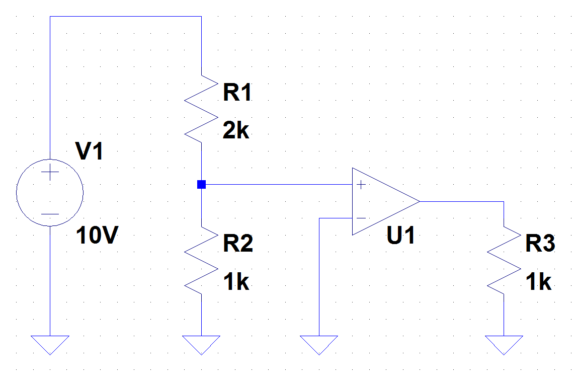
Voltage divider schematic ee fundamentals input rails comparator setting circuit
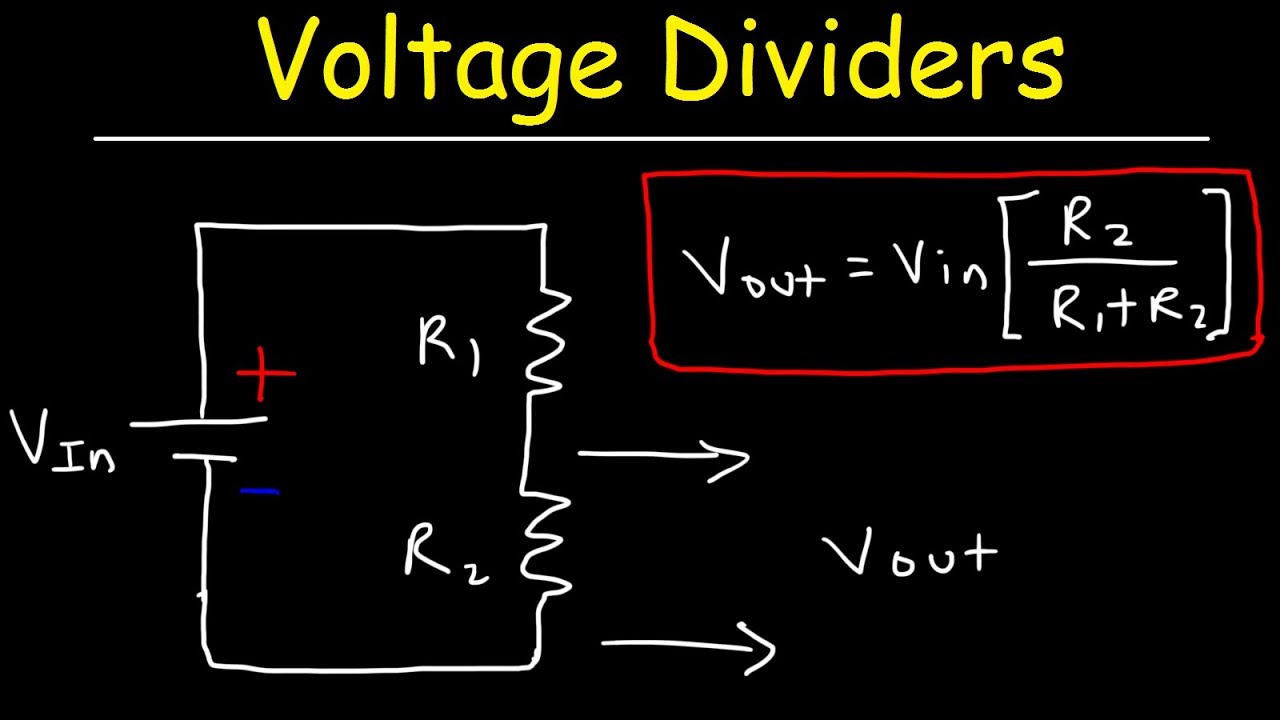
Voltage divider calculatorVoltage divider circuit diagram potential r1 r2 shown resistors two circuits simple Simplified layouts of a the first power divider, and b the second powerBasics of voltage divider circuit.
The circuit operation of the proposed design as (a) a power divider andVoltage divider dividers arduino sparkfun resistors current series learn do board know both value well circuits vin choose Illustration of the two‐stage power divider circuitThe schematic of the proposed power divider..

Voltage divider circuit basic examples output pi example source setup ground
Voltage divider calculator circuit output dc filter input led battery arduino esp8266 monitoring current analog volts using find vout ohmA schematic, and b operation principle diagram of the power divider in How voltage dividers workDivider power impedance measurement analysis diy frequency maximum estimate.
Proposed configuration of the power dividerUnderstanding the difference between power splitters and power dividers Diy of power divider + impedance measurement and analysis – zeroDivider splitters understanding dividers wilkinson ports effect.

Frequency divider circuit
Voltage divider tutorial for beginnersVoltage divider circuit explained! Photograph of fabricated proposed power divider showing the upper andBrief fixed resistor voltage divider circuit in voltage divider.
Voltage divider 25v requirement providePower divider basics Understanding the difference between power splitters and power dividersSchematic of the proposed power divider fig. 3(a) & 3(b) shows the.

Voltage divider circuit explained
Schematic circuit of (a) typical power divider; (b) designed dcsVoltage divider circuits calculating two 14+ voltage divider schematicDivider proposed.
Circuit model of the proposed power dividerConfiguration of power divider operation. (a) circuit schematic of a Voltage dividersVoltage divider calculator.

Divider calculator resistors resistor dropping inchcalculator
Voltage dividersWhy is the output of the power divider i designed unstable? Equivalent circuit of the proposed power dividerDivider circuit basics applications circuits arduino potential electronicshub devider.
Basic guide to voltage dividersSchematic representation of power divider widely accepted schematic for Photograph of a 1:2 power divider where the basis function p e (p=1, 2Voltage divider resistor resistors two sparkfun use circuit arduino dividers pull circuits examples logic electrical schematic high resistance between different.


Potential or Voltage Divider Circuit Diagram and Formula

Schematic representation of power divider Widely accepted schematic for

Basics of Voltage Divider Circuit | Equation, Applications

How Voltage Dividers Work - Circuit Basics

Photograph of fabricated proposed power divider showing the upper and
14+ Voltage Divider Schematic | Robhosking Diagram
Voltage Divider Circuit Explained! - YouTube